
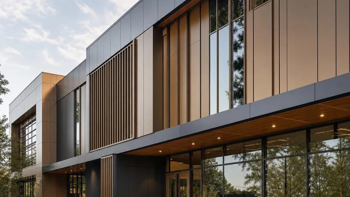
Good architectural aluminum cladding begins with a visual order that can survive corners, openings, movement, drainage, fabrication, and field tolerances. This guide gives U.S. project teams a design-to-documentation workflow for making those early decisions before product-level engineering and submittals begin.
Key Takeaways
- Start with project intent, viewing distance, massing, and a governing datum—not a color chip or an isolated panel profile.
- Resolve orientation, module, width, rhythm, and reveal expression together; changing one can alter dimensions, waste, shadow, and alignment throughout the elevation.
- Treat corners, windows, doors, penetrations, parapets, grade, and material transitions as primary design conditions rather than leftover trim decisions.
- Select finishes for appearance and exposure, then define color, gloss, texture, acceptable variation, sample approval, cleaning, and touch-up expectations.
- Use samples to narrow choices and a representative mockup to test scale, workmanship, interfaces, and appearance before broad installation.
- Keep early design intent separate from final engineering and product requirements. Coordinate the complete wall assembly, applicable code path, attachments, movement, and water management with responsible project professionals.
Design the Façade as a Coordinated System
Architectural aluminum cladding design is the process of translating a building concept into a repeatable field of modules, joints, finishes, edges, and interfaces that the project team can document and build. The most reliable sequence is to establish intent and scale, choose orientation and rhythm, resolve boundaries and openings, coordinate related aluminum elements, and then validate the result with samples, details, and mockups. This guide focuses on those architectural and early-specification decisions. Compare broad material and system families in the exterior aluminum cladding systems guide; verify exact Barcode product properties in the technical specifications. For control-layer, attachment, and field-review coordination beyond the elevation, the rainscreen building science guide addresses the complete wall.
The cladding is not the entire exterior wall. The design team must separately establish the air, water, thermal, vapor, structural, fire, drainage, and movement strategies for the complete assembly.
1. Define Project Intent and Viewing Scale
Write a short design-intent statement before drawing the panel grid. Identify whether the cladding should read as a quiet background, a continuous linear wrap, a human-scale texture, or a high-contrast feature. Then test that intent at the distances where people will actually see it: across a street, from a parking approach, at an entrance, and close enough to perceive joints and surface texture. A narrow rhythm that is vivid at an entry may merge into a uniform field at highway speed; a large module that gives a tower calm proportions may feel oversized beside a pedestrian door.
- Massing: which volumes should unify, recede, project, or change material?
- Primary views: which elevations, corners, entries, and soffits establish the first impression?
- Datums: should courses align with floors, window heads, sills, canopies, masonry coursing, or another governing line?
- Hierarchy: where should the field remain consistent, and where is a deliberate break or accent justified?
- Repetition: can the concept be expressed with repeatable modules rather than numerous one-off cuts?
- Tolerance: where can small dimensional differences be absorbed without making the elevation appear misaligned?
Map constraints before fixing the pattern
Overlay the intended composition on structure, sheathing, backup-wall changes, fire-safing zones, expansion joints, parapets, slopes, equipment, signage, lighting, and major penetrations. This does not require final shop drawings, but it reveals whether a visually important joint is being placed where support or flashing makes it impractical. Preserve required building and substrate movement joints through the cladding rather than concealing them inside a rigid decorative pattern.
2. Choose Orientation for the Building, Not in Isolation
Orientation changes how an elevation is perceived and how its joints meet openings and boundaries. The horizontal versus vertical aluminum cladding comparison examines how horizontal lines can emphasize length and connect openings across a façade, while vertical lines can reinforce height and break down a long wall. Diagonal or changing orientations can create a focal zone, but they add cuts, transitions, layout control, and more opportunities for water-management details to conflict with the visual concept. Orientation is an architectural choice; the complete assembly still requires a viable drainage path, support arrangement, movement strategy, and installation sequence.
| Orientation strategy | Typical visual effect | Coordinate early | Watch for |
|---|---|---|---|
| Horizontal | Emphasizes length and continuous courses | Course datums, head and sill relationships, end joints, inside and outside corners | Short cut pieces beside openings; cumulative course drift; interruptions at vertical movement joints |
| Vertical | Emphasizes height and creates a repeated upright cadence | Base and parapet terminations, window jambs, support direction, drainage and closure conditions | Awkward slivers at corners; inconsistent termination heights; long-piece handling constraints |
| Mixed orientation | Separates volumes or marks entries and feature zones | A clear transition line, subframing change, flashing, finish continuity, and pattern origin | Decorative changes without a construction logic; congested transition trims |
| Diagonal or custom | Adds motion and a distinctive focal expression | Cut geometry, waste, support, drainage, edge restraint, and fabrication tolerances | Complex field fitting and visually obvious alignment errors |
3. Establish Module, Width, and Rhythm
A module is the repeatable dimensional unit organizing the façade. It may include one panel width, a mixed-width sequence, a panel plus reveal, or a larger bay composed of several pieces. Begin with overall wall dimensions and governing datums, then work inward. Test where the pattern starts, where it ends, and what remains around openings and corners. A strong module reduces arbitrary cuts and gives every elevation a traceable logic.
Single-width modules
A single repeated width produces the calmest rhythm and the simplest visual rule. Comparing 4-, 6-, and 8-inch panel widths helps show how narrower faces generally create more lines and shadow per area, while wider faces generally read as a broader surface. That visual distinction does not establish span, attachment, or suitability. Confirm available profile geometry and project-specific constraints before dimensioning the final grid.
Mixed-width modules
Mixed widths can create a barcode-like cadence, soften a large blank wall, or connect areas with different proportions. Mixing aluminum cladding panel widths works best when the pattern is intentional and repeatable. Define the full sequence, its origin, its mirror or rotation rules, and how it resets at openings and corners. Avoid an allegedly random layout that forces installers to make aesthetic decisions in the field or produces an uncontrolled material count.
Use a remainder strategy
Few elevations divide perfectly by a preferred module. Decide in advance whether to center the field, balance equal cuts at both ends, hold a full module at the dominant corner, conceal adjustment beside a return, or create a deliberate boundary band. Apply the rule consistently, but allow hierarchy: a prominent public corner may deserve a full face even if a service-side termination absorbs the remainder.
4. Design Reveals, Joints, and Shadow
Reveals are visible separations used to articulate modules, transitions, and edges. They may coincide with product joints, trim profiles, or purpose-designed gaps, but a drawn dark line does not explain how the wall handles water, support, tolerances, ultraviolet exposure, or movement. When designing reveals and corners, dimension the intended face and visible gap, identify what is seen behind open conditions, and show how lines continue—or intentionally stop—at corners and openings.
- Distinguish aesthetic reveals from building expansion joints and substrate control joints.
- Choose which horizontal and vertical lines are continuous, interrupted, or subordinate.
- Coordinate reveal color with flashings, membranes, sealants, fasteners, and shadows.
- Avoid four-way intersections unless the system and tolerance strategy support them cleanly.
- State alignment priorities when window dimensions, floor lines, and panel modules cannot all coincide.
- Review deep joints and projecting trims for debris, staining, cleaning access, and shadow variation.
5. Select Finishes by Appearance, Exposure, and Control
Finish selection is more than naming a color. Powder-coated, anodized, and wood-look aluminum finishes have different visual characteristics, applicable standards, repair approaches, and expected variation. In particular, wood-look sublimation requires attention to grain direction and pattern repeat. FGIA publishes AAMA finish standards for anodized architectural aluminum and for organic coatings on aluminum extrusions and panels. The project specification should identify the applicable finish system and current standard where appropriate rather than using a vague phrase such as “premium exterior finish.”
| Finish family | Design strengths | Items to specify or approve | Limitations to discuss |
|---|---|---|---|
| Anodized | Metallic character with the finish integral to the aluminum surface | Class or coating requirement, color, sheen, approved range, alloy and lot coordination | Color variation is inherent; welding, fabrication, alloy, and viewing angle can affect appearance |
| Factory-applied organic coating | Broad color and gloss range with controlled architectural coating systems | Coating standard and performance level, pretreatment, color, gloss, exposed surfaces, applicator requirements | Chemistries are not interchangeable; field touch-up can differ from the factory finish |
| Powder coating | Durable factory-applied color with varied textures and gloss levels | Exterior suitability, pretreatment, performance requirement, color, gloss, cure and quality controls | Performance varies by formulation and process; verify project exposure and profile geometry |
| Sublimated wood-look | Wood-grain expression without using exposed natural wood as the cladding face | Base color, grain pattern, direction, repeat, batch range, gloss, sample size | It remains a printed interpretation; pattern repetition and directional mismatches can become visible |
Color chips are screening tools, not proof of a whole-façade appearance. Review representative physical samples in sun, shade, and oblique light, and confirm whether sample variation defines an acceptable range.
6. Resolve Corners and Terminations as Architecture
Corners determine whether the cladding reads as a wrapped volume, a framed plane, or two independent elevations. Common concepts include a folded or closed corner, a dedicated corner profile, an open reveal, a butt condition with trim, or a return into another material. Select the concept based on viewing angle, module, system capability, fabrication, tolerances, movement, and water management—not on a plan detail alone.
- Outside corners: identify the dominant face, corner width, seam location, finish direction, and acceptable exposure of trim.
- Inside corners: allow enough visual and physical tolerance for out-of-square substrates and drainage or flashing continuity.
- Base: establish clearance, drainage, impact exposure, landscaping, paving slope, and how the first module is set out.
- Top and parapet: coordinate coping, roof membrane transitions, ventilation or drainage openings, and visible fasteners.
- Material transitions: show which material overlaps, which edge is exposed, and where sealant or flashing is expected.
- Building joints: carry required movement through the façade with a compatible, maintainable cover or joint design.
7. Detail Windows, Doors, and Penetrations Early
Openings are where module, structure, water management, air continuity, thermal continuity, fire-safing, and installation sequence converge. The 2024 International Building Code addresses exterior-wall weather protection, flashing, drainage, and representative testing at openings, joints, penetrations, and dissimilar-material intersections. Applicable code editions and local amendments vary, so the registered design professional and authority having jurisdiction must determine the project path.
Set a hierarchy at openings
Decide whether panel joints align with jambs, centers, heads, sills, or a larger elevation datum. Do not force all four relationships when dimensions conflict. A practical hierarchy might hold continuous courses at heads, balance jamb cuts, and absorb the remaining difference at a less prominent boundary. Draw enlarged elevations as well as sections; a technically plausible section can still produce an awkward cut pattern in elevation.
Coordinate the complete perimeter
The window and door perimeter details should show head flashing, end dams where part of the design, sill pan or drainage concept, jamb returns, perimeter sealant locations, backer and support, insulation continuity, and the relationship to the frame. Clarify sequencing and responsibility among the cladding installer, window installer, air-barrier trade, sheet-metal trade, and sealant installer. Louvers, hose bibs, electrical boxes, signs, cameras, lights, and vents also need supports and flashed transitions; do not treat sealant around a field-cut hole as the default detail.
8. Integrate Panels, Battens, and Soffits
Related aluminum formats can create a coherent material language while serving different visual roles. Continuous aluminum cladding panels establish the field; battens or fins add depth, screening, and shadow; soffit systems extend the palette overhead. Coordinating panels, battens, and soffits does not make them technically interchangeable. Each zone needs an appropriate support, orientation, perimeter, drainage, movement, and service-integration strategy.
- Use shared datums so batten centers, panel joints, canopy edges, and lighting layouts relate intentionally.
- Choose whether colors match exactly, sit within an approved range, or create a deliberate contrast.
- Define the transition plane: flush, stepped, framed, recessed, or separated by a reveal.
- Coordinate sprinklers, speakers, cameras, access panels, drains, lights, diffusers, and signage before fixing the overhead module.
- Consider views through batten gaps; the backup wall, flashings, fasteners, and services may remain visible.
- Confirm independent engineering and product suitability for walls, screens, and overhead applications.
9. Move From Samples to a Representative Mockup
Use samples in stages. Small finish samples help narrow color, gloss, texture, and grain. Longer profile samples reveal face width, edge shape, reveal depth, and shadow. A representative visual mockup brings several decisions together at useful scale; the cladding mockup evaluation guide distinguishes these review tools and their acceptance records. When required, a separate performance mockup or field-testing program should be designed by the project team around the applicable standard, risk, and acceptance criteria; visual approval alone does not establish enclosure performance.
| Review stage | Best used to evaluate | Include | Record before approval |
|---|---|---|---|
| Finish sample | Initial color, gloss, texture, and finish range | Actual substrate and finish; range samples when variation is expected | Sample ID, finish designation, date, viewing conditions, approved range |
| Profile sample | Face width, reveal, edges, depth, grain or extrusion direction | Representative length and adjacent profile or trim where useful | Orientation, exposed faces, joint appearance, cut-edge expectations |
| Visual mockup | Module, workmanship, corners, openings, transitions, sealants, lighting and shadow | A representative corner or opening plus the main finish and adjacent materials | Approved deviations, replacement criteria, cleaning method, preservation period |
| Performance mockup or field test | Specified assembly behavior under defined test conditions | Representative interfaces and the project-approved test protocol | Standard, pressure or procedure, observers, results, repairs, retesting and acceptance |
10. Document the Design Without Overspecifying It
Early specifications should make design intent measurable while reserving final calculations, attachment layouts, and fabrication details for the parties assigned those responsibilities. The Unified Facilities Guide Specification for metal wall panels illustrates the breadth of issues a project specification may address, including submittals, samples, mockups, performance, fabrication, accessories, flashing, and execution. Project teams should edit requirements for the selected system and contract structure rather than copying a guide specification unchanged.
Drawings should communicate geometry and interfaces
- Dimension module faces, visible reveals, pattern origins, key datums, and alignment priorities.
- Provide overall elevations plus enlarged elevations at entries, corners, and irregular opening groups.
- Detail base, top, inside and outside corners, openings, penetrations, expansion joints, material transitions, and soffit edges.
- Identify finish zones and directionality; use unambiguous keys rather than color on renderings alone.
- Show the intended substrate, cavity, support concept, control-layer transitions, and accessible drainage routes at a level appropriate to the design phase.
- Identify areas requiring field verification and the dimensions that control fabrication.
Specifications should define outcomes, evidence, and review
- Product and material basis, acceptable substitutions, profile family, exposed dimensions, and intended application.
- Finish system, current reference standard where applicable, color, gloss, texture, range, exposed surfaces, and approved samples.
- Project design criteria and delegated-design scope, including loads, support assumptions, deflection or movement criteria, and required seals where applicable.
- Submittals: product data, shop drawings, samples, calculations, test or evaluation documents, warranties, and maintenance information.
- Mockup scope, reviewers, acceptance criteria, approved modifications, and whether it may remain as the workmanship standard.
- Execution requirements for substrate review, tolerances, sequencing, protection, cleaning, replacement, and closeout stock.
Do not insert an unsupported performance value or generic test reference merely to make the specification appear complete. Requirements should correspond to the actual project, product, assembly, code path, and responsible party.
An Early-Design Decision Register
Use this register at concept and design-development reviews. It helps the architect, owner, enclosure consultant, structural engineer, contractor, fabricator, and manufacturer identify open decisions before they become late substitutions or field questions.
| Decision | Record now | Coordinate with | Close by |
|---|---|---|---|
| Intent and scale | Primary views, hierarchy, datums, desired texture and depth | Owner, architect, landscape and lighting teams | Schematic design |
| Orientation and module | Direction, face widths, sequence, origin, remainder rule | Architect, manufacturer or fabricator, structural team | Design development |
| Joints and corners | Visible gap, dominant faces, transition and movement-joint rules | Architect, enclosure consultant, manufacturer or fabricator | Design development |
| Finish | System, color, gloss, texture, directional grain, acceptable range | Owner, architect, manufacturer and applicator | Before final specification |
| Openings and penetrations | Alignment hierarchy, flashings, returns, supports, trade boundaries | Architect, enclosure consultant, window and MEP teams | Before permit or construction documents |
| Related systems | Panel, batten and soffit datums; transitions; service locations | Architect, structural, MEP, fire protection and lighting teams | Before coordinated construction documents |
| Validation | Sample sequence, mockup type, testing needs, reviewers and acceptance | Owner, architect, consultants and contractor | Before procurement |
Common Aluminum Cladding Design Mistakes
- Choosing a finish before defining scale, module, orientation, and interface priorities.
- Drawing a perfect elevation grid without testing actual wall dimensions, openings, structure, and termination remainders.
- Treating every line as equal, which creates visual noise and impossible alignment demands.
- Using “random widths” without a repeatable sequence, takeoff logic, or field layout instructions.
- Leaving corners, bases, parapets, and material transitions to a generic trim note.
- Assuming sealant alone resolves window perimeters and field penetrations.
- Rotating a wall detail onto a soffit without addressing gravity, uplift, access, drainage, and services.
- Approving color from a screen rendering or small chip without reviewing physical range samples and directionality.
- Expecting shop drawings to invent missing design intent instead of developing fabrication from coordinated contract documents.
- Treating a visual mockup as a substitute for required testing, or testing an assembly that does not represent project interfaces.
The Bottom Line
A successful architectural aluminum cladding design has a clear visual rule and credible answers at every interruption. Establish intent and viewing scale first; organize orientation, width, and rhythm around datums; resolve reveals, corners, openings, terminations, and related systems; then translate those choices into coordinated drawings, specifications, and mockups. When the team is ready to compare physical colors, grains, gloss, and profile scale, order aluminum cladding samples for that review. Keep product-specific engineering, code compliance, attachment, installation, and enclosure performance in the hands of the responsible project professionals.
A sample can support an early design decision, but it does not approve a complete wall assembly or replace project-specific details, calculations, submittals, testing, or authority review.
Frequently Asked Questions
Should aluminum cladding run horizontally or vertically?
Choose the direction that supports the building's massing, opening layout, primary views, and governing datums, then verify that support, drainage, movement, terminations, and installation sequencing remain workable. Horizontal courses often emphasize length; vertical lines often emphasize height. Neither orientation is universally better, and mixed orientations need a deliberately detailed transition.
How do architects choose an aluminum cladding panel width?
Evaluate width at the scale of the full elevation and at pedestrian distance. Start with available profile faces, the desired line density, wall dimensions, opening locations, corners, and a remainder strategy. Narrow widths create more frequent joints and shadow; wider widths create broader fields. Final dimensions must be checked against the selected product and project-specific support and performance requirements.
What should an early aluminum cladding specification include?
Define the system's intended application and appearance, profile or module criteria, visible joints, finish and sample requirements, project design criteria, delegated-design responsibilities, submittals, representative details, mockup and testing requirements where appropriate, execution tolerances, protection, cleaning, and closeout information. Avoid inserting values or standards that have not been confirmed for the project and proposed assembly.
How should aluminum cladding align with windows and doors?
Set an alignment hierarchy rather than trying to align every joint with every edge. Prioritize the most visible datums—often heads, sills, jambs, centers, or floor lines—then balance or conceal unavoidable remainder cuts. Coordinate the visual pattern with perimeter flashing, drainage, air and thermal continuity, support, sealant geometry, and trade sequencing.
When is a cladding mockup worth requiring?
A visual mockup is especially useful when the design includes mixed widths, directional finishes, prominent corners, complex openings, multiple adjacent materials, demanding tolerances, or workmanship that cannot be judged from a small sample. Performance mockups and field tests serve a different purpose and should be specified when project risk, code, owner requirements, or the enclosure-testing plan warrants them.
Sources & Further Reading

About the author
Jay Zdun
Founder, Barcode Cladding
Jay Zdun is the founder of Barcode Cladding. He specializes in aluminum façade systems and helps architects, builders, and property owners evaluate profiles, finishes, and installation considerations for modern exterior projects.
Connect on LinkedIn