
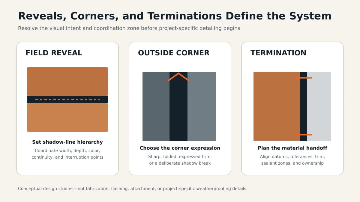
Set a small number of clear edge rules, test them at every change in plane, and document where profiles stop, turn, align, or give way to another material.
Key Takeaways
- Treat reveals and edges as a coordinated visual system rather than a collection of isolated trim choices.
- Decide which lines continue, turn, stop, or deliberately shift before developing enlarged details.
- Test outside corners, inside corners, bases, tops, and material changes against the same elevation datums.
- Use drawings, schedules, and mockups to communicate intent; do not rely on a generic note such as “manufacturer standard.”
- The visible edge strategy does not establish drainage, structural adequacy, fire performance, or code compliance.
A coherent cladding edge strategy starts by defining how the field module meets every interruption. Establish the intended hierarchy of joints, corners, bases, tops, and material transitions, then test that hierarchy in elevation and enlarged details as part of the architectural aluminum cladding design workflow. This guide supports visual and documentation decisions; it does not replace project details, manufacturer review, enclosure design, or the separate choice between open- and closed-joint wall strategies.
Begin With a Line-Hierarchy Diagram
Before selecting corner or termination components, mark the lines that organize the elevation: primary module joints, secondary reveals, opening datums, floor or canopy lines, and boundaries between materials. Rank them by visual importance. A primary line may continue across a large field while a secondary line yields at an opening or return. This simple diagram gives the team a shared rule for resolving conditions that were not prominent in the concept rendering.
Decision Table: Define Each Edge Before Detailing
Use this table as an early drawing checklist. The last column identifies the decision that should be explicit rather than left to inference.
| Condition | Visual question | Coordination question | Document explicitly |
|---|---|---|---|
| Field reveal | Feature line or quiet joint? | What is visible in the recess? | Alignment, intended expression, and finish relationship |
| Outside corner | Crisp edge, expressed trim, or open return? | How do modules meet on both faces? | Corner type and controlling face or datum |
| Inside corner | Continuous wrap or deliberate shadow break? | Is there room for installation and tolerance? | Return, recess, and adjacent cut condition |
| Base | Floating shadow or visually closed edge? | How does the wall meet grade or paving? | Visible termination and relationship to adjacent work |
| Top | Does cladding disappear, cap, or return? | How does it meet parapet, roof, or soffit work? | Top profile, datum, and trade interface |
| Material change | Flush transition or expressed separation? | Which assembly and trade establishes the line? | Joint ownership, depth, and finish |
Resolve Outside and Inside Corners as Paired Elevations
A corner belongs to two surfaces. Develop both elevations and the plan detail together so a clean solution on one face does not leave an unusable sliver or broken course on the other. Outside corners often become strong focal lines; inside corners tend to accumulate tolerance, shadow, and installation-sequence issues. Decide whether each corner should disappear into the field, read as a separate frame, or create an intentional recess. Then keep that role consistent where the condition repeats.
Give Bases, Tops, and End Conditions a Visual Role
The base establishes whether the wall appears grounded or lifted; the top establishes whether it reads as a capped object, a plane continuing behind another element, or a surface turning overhead. Side terminations can frame a field or allow it to dissolve into an adjacent material. Review these edges at realistic viewing distances and from oblique angles. Also identify where visible closures, screens, backing, sealants, fasteners, or unfinished return surfaces could interrupt the intended effect.
Coordinate Reveals Without Redesigning the Wall Assembly
A visible reveal is not, by itself, a drainage detail or weather seal. Behind the appearance, the project still needs continuous control layers, support, movement accommodation, and paths for water to leave where applicable. The open-joint versus closed-joint cladding choice is a separate system-selection and building-science question. Keep the aesthetic decision and the enclosure decision connected but distinct. The project architect and enclosure professionals should define the complete assembly, while the cladding drawings clearly show how the visible profile relates to it.
Document Intent Across Plans, Elevations, and Details
Use elevations to establish continuity and hierarchy, plans and sections to establish depth and interfaces, and enlarged details to identify the intended edge family. Give corner and termination types stable identifiers, reference them consistently, and show atypical conditions rather than assuming a typical detail will stretch to fit. Notes should describe the intended relationship—aligned, recessed, flush, continuous, or intentionally offset—without dictating an unverified fabrication solution.
- Overlay module lines on every elevation, including small returns.
- Key each edge type to at least one enlarged plan or section.
- Identify the controlling datum when adjacent construction varies.
- Coordinate finish and exposed-backside expectations at returns.
- Record unresolved interfaces in a responsibility matrix or detail log.
Use Samples and Mockups to Review Transitions
Flat color chips cannot show corner scale, reveal shadow, return depth, or how adjacent profiles meet. Review representative assemblies that include the transition being decided; Barcode Cladding samples can help compare finish and profile relationships before a larger review. The Metal Construction Association notes that visual acceptance criteria deserve explicit attention alongside other project requirements. Define the viewing conditions and acceptance topic before review; sunlight, orientation, profile geometry, and proximity can change perception.
Balance Simplicity With Project-Specific Conditions
A small edge vocabulary can improve visual consistency and drawing clarity, but forcing one detail onto incompatible conditions can create awkward cuts or hidden conflicts. The same hierarchy should account for cladding around windows and doors and for edges where panels, battens, and soffits meet. Conversely, a custom response at every corner increases review and coordination effort. Favor repeatable rules, then identify genuine exceptions caused by geometry, exposure, adjoining assemblies, access, or sequence. Neither minimal trim nor expressed trim is universally superior.
These principles do not supply project dimensions, flashing instructions, engineering, tested performance, or code compliance. The responsible design professionals and system providers must resolve and review each project condition.
Frequently Asked Questions
Should every cladding corner use the same visual treatment?
Not necessarily. A building may distinguish primary volumes, recessed entries, and service areas, but each variation should have a stated reason and a repeatable rule. Too many unrelated corner types can make the elevation look accidental and complicate documentation.
Should a reveal align through an outside corner?
Only when that alignment supports the design intent and the selected system can resolve the turn. Draw both faces together, consider the normal viewing angles, and confirm the resulting face dimensions and corner geometry with the system supplier.
Can a standard trim solve every base and top condition?
No. Exposure, adjacent materials, cavity boundaries, support, drainage, parapets, soffits, and construction sequence vary. Standard components may be useful, but the project team must integrate them into project-specific enclosure details.
How should corner and termination intent be reviewed?
Use coordinated elevations and enlarged details first, then review representative samples or a mockup that includes real transitions. State what is being reviewed—line continuity, shadow depth, finish relationship, cut quality, or interface with adjacent work—so comments are actionable.
Sources & Further Reading

About the author
Jay Zdun
Founder, Barcode Cladding
Jay Zdun is the founder of Barcode Cladding. He specializes in aluminum façade systems and helps architects, builders, and property owners evaluate profiles, finishes, and installation considerations for modern exterior projects.
Connect on LinkedIn