
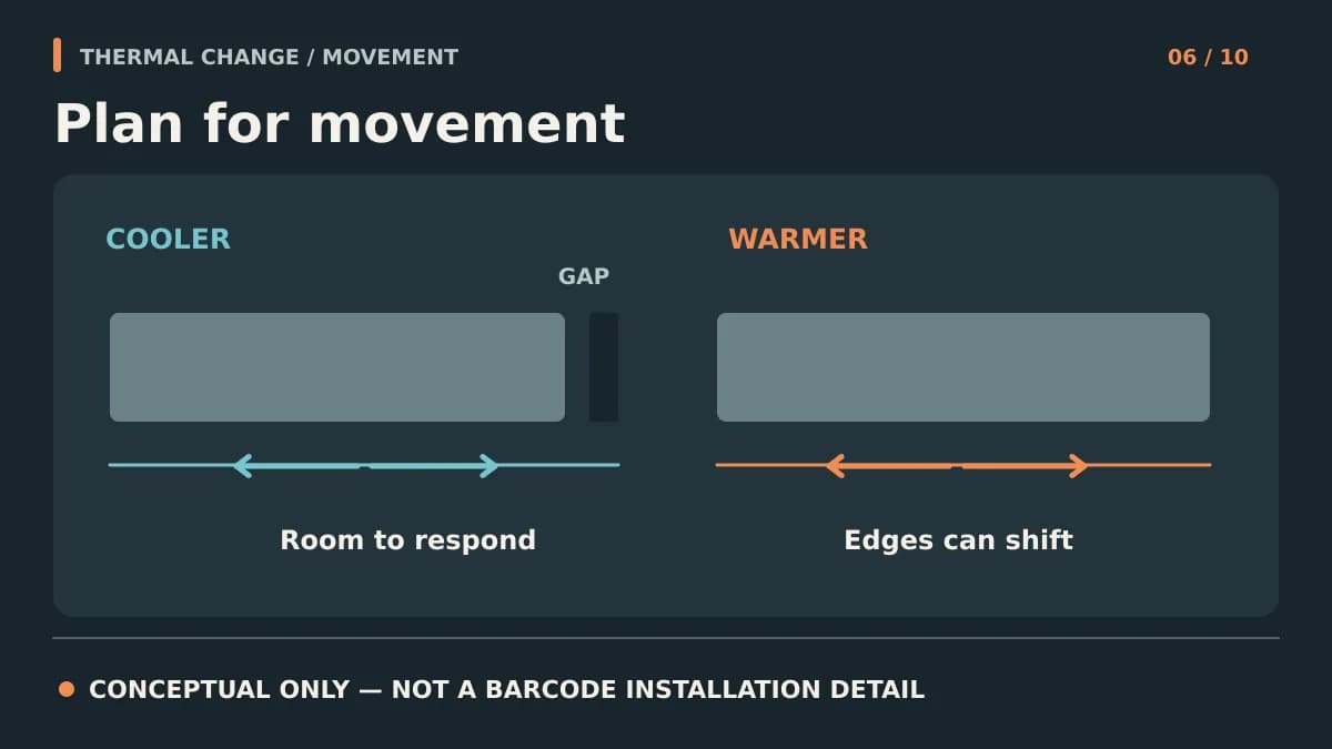
A clean reveal cannot do its job if the panel, rail, and building move differently and every connection is restrained. Map movement before finalizing the joint detail.
Key Takeaways
- Set a panel-run strategy before cutting or clipping panels; restraint and permitted movement must be intentional.
- The required joint is project- and selected-profile-specific, not a universal gap taken from a blog or catalog.
- Review sunny and shaded runs, corners, openings, and building joints separately because they constrain motion differently.
- Movement clearance must coexist with secure attachment, weather management, and an acceptable reveal.
Aluminum changes length as its temperature changes, while the supporting wall, rail, and adjoining materials may move by different amounts. The practical question in the complete aluminum rainscreen assembly is not whether to 'leave a gap' but where movement is intentionally allowed, where loads are resisted, and what happens at the end of a run. Use this guide to frame the drawing review; it does not specify a Barcode fixing detail or expansion allowance.
Map the Run, Not Just an Isolated Joint
On each elevation, mark panel orientation, segment ends, corners, interruptions, changes of plane, and the building's own movement joints. For a long uninterrupted run, identify the point that locates the panel and the locations that can accommodate its relative movement under the approved system design. At pipes or fixtures, coordinate penetration flashing with the moving run. Do not presume that a concealed clip automatically slides or that every rail joint lines up with a panel joint. Ask for the selected-profile detail that distinguishes restraint from allowance.
- Mark the reference point for each run and any planned changes in direction.
- Check the interface with window frames, flashing, trim, soffit edges, and adjoining materials.
- Show movement at structural or substrate joints rather than bridging them casually.
- Record the installation-temperature assumption used in a project-specific calculation.
Make the Joint Decision Verifiable
A designer can calculate an indicative free thermal length change using the selected alloy's documented coefficient, the effective run length, and the anticipated temperature range. That is only a starting input: actual clearance also depends on the profile, fixing geometry, tolerances, loads, trim engagement, and differential substrate movement. Do not translate an illustrative calculation into a universal joint dimension. Keep a written selected-profile approval trail before approving shop drawings or ordering precut lengths; the NIBS building enclosure commissioning guideline supports reviewing movement and interface details before concealment.
| Condition | Movement question | Required review |
|---|---|---|
| Long panel run | Where is the reference and where can length change occur? | Selected panel / clip details and calculated allowance |
| Outside corner | Can adjacent faces move independently without collision? | Corner accessory and both elevations |
| Opening head or jamb | Will trim and flashing still work as panel ends move? | Opening detail and water exit path |
| Building movement joint | Does cladding respect the underlying joint? | Structural/enclosure joint detail |
Select the Barcode Profile Before Freezing the Edge
Barcode's aluminum panels and starter, clip, corner, end-cap, and joint accessories provide a vocabulary for panel terminations. Physical samples can help the team judge the visible reveal, while technical review must confirm selected current profile compatibility and the actual movement detail. The public catalog is a starting point for accessory conversations, not permission to assume all profile dimensions or approved installation gaps. Record any difference between catalog and online information for direct confirmation.
Hold Point: Trial the Hardest Joint
Mock up a representative corner or opening with the selected accessories. Confirm engagement, alignment, tolerances, fixing intent, drainage, and appearance before repeating it across the elevation; installation quality-control hold points should include this condition. An architectural cladding mockup can establish visual acceptance separately from engineered movement capacity. Inspect the condition after installation without treating a visually neat joint as proof of that capacity. Coordinate the independently moving panel with its subframing supports. The project team remains responsible for the complete enclosure and structural movement design; Barcode review covers the chosen product information, not blanket assembly approval.
Frequently Asked Questions
What expansion gap should I leave for Barcode aluminum cladding?
There is no universal number. The selected profile, run length, temperature assumptions, fixing behavior, adjacent materials, and approved project details determine the clearance.
Does a concealed clip automatically let a panel expand?
No. The system's actual clip engagement, fixed and movable locations, and installation details need confirmation; a concealed appearance alone says nothing about movement capacity.
Can panels cover a building expansion joint?
Do not bridge a structural or enclosure movement joint without an approved joint detail that preserves the underlying movement and weather-control strategy.
Why review movement at windows?
A panel end or trim at a jamb or head can meet a relatively different-moving frame and flashing assembly; the detail must retain clearance, attachment, and drainage as designed.
Sources & Further Reading
- NIBS — Building Enclosure Commissioning Process, Guideline 3-2012
- GSA — 2024 P100 Building Enclosure Training
- Barcode Cladding — 2026 Catalog (confirm current selected profile)

About the author
Jay Zdun
Founder, Barcode Cladding
Jay Zdun is the founder of Barcode Cladding. He specializes in aluminum façade systems and helps architects, builders, and property owners evaluate profiles, finishes, and installation considerations for modern exterior projects.
Connect on LinkedIn