
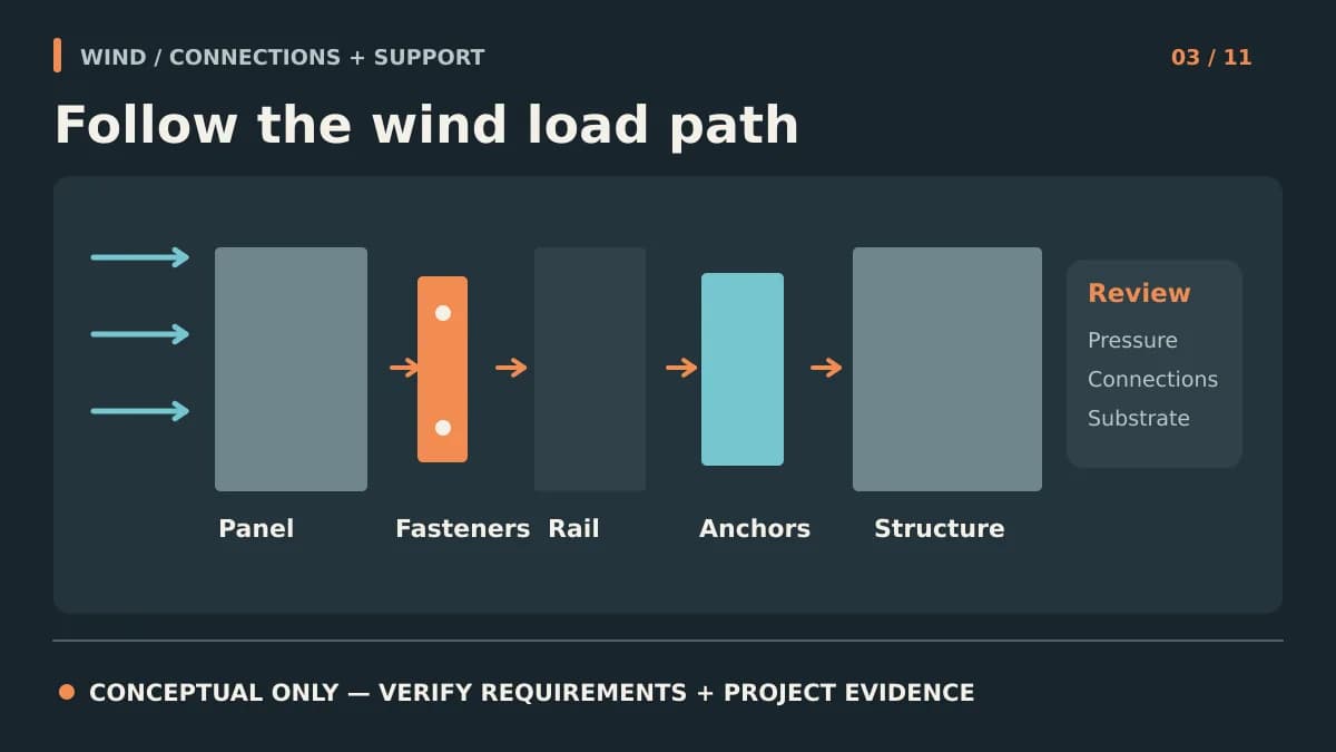
A wind-speed number is not a panel rating. Follow pressure through panels, clips, rails, fasteners, and backup construction.
Key Takeaways
- Project-specific component-and-cladding pressures are not the same as a nominal design wind speed.
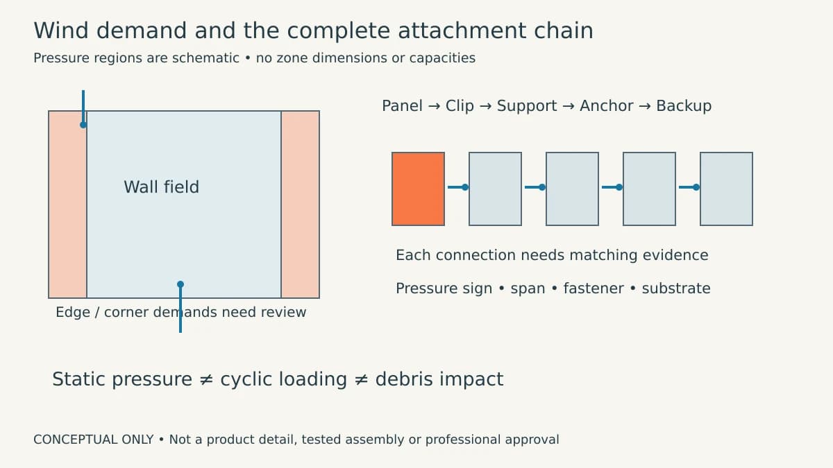
- The load path includes the panel, clips or fasteners, subframing, anchors, and structural backup.
- Match the tested specimen, span, boundary conditions, and pressure direction to the proposed system before relying on a report.
- A product sample establishes appearance, never structural resistance.
A panel may look stiff in hand yet behave differently across a long span at a building corner. Wind design therefore begins with the project's governing pressures, not with a generic “high-wind” label. The building professional establishes the loads; the façade team shows how the selected cladding and attachment system resists them. Keep structural review within the wider cladding performance, codes, and lifecycle evidence plan. This is a workflow for asking better questions, not an engineering schedule for a Barcode profile.
Find the Actual Components-and-Cladding Pressure
ASCE/SEI 7-22 Chapter 30 addresses wind loads on components and cladding. An engineer accounts for the applicable adopted edition, site, exposure, height, geometry, effective wind area, enclosure classification, and zones. Corners and edges can require different treatment from the field of a wall; positive inward pressure and negative suction may demand different checks. A basic wind speed printed on a permit drawing is an input, not an allowable pressure for a clip. Request a project pressure schedule with zones, units, directions, and design criteria before reviewing supplier spans.
Decision Table: Match Evidence to the Question
ASTM E1592 explicitly covers structural performance of sheet-metal panels and anchor-to-panel attachments in roof or siding systems under uniform static air pressure difference. ASTM E330/E330M covers exterior windows, doors, skylights, and curtain walls; it should not be presented as a universal test of all siding systems. Ask which test scope genuinely applies to the proposed construction. A laboratory report records the specimen and observed behavior, not an unrestricted certificate for any span or attachment arrangement.
| Evidence | Useful for | Check before using | Not a substitute for |
|---|---|---|---|
| Project wind-pressure schedule | Loads at field, edge, and corner zones | Code edition, exposure, effective area, both directions | Product resistance evidence |
| ASTM E1592 report | Tested sheet-metal roof or siding panel/anchor response to uniform static pressure | Specimen, attachments, spans, boundary conditions | Every different wall configuration |
| ASTM E330/E330M report | Tested curtain wall/window/skylight specimen structural response | Whether test scope and specimen match this façade | Unexamined panel-to-backup load path |
| Project connection calculations | Fastener, rail, anchor and substrate demand/capacity | Actual backup and edge distances | Independent review of untested panels |
Trace the Load All the Way to Structure
Suction pulls on panels and transfers through locks, clips or direct fasteners, cladding subframing, bracket anchors, and the backup wall. A strong panel does not remedy a weak anchor, thin sheathing, insufficient embedment, or an unverified clip engagement. Check both local panel bending and concentrated connection loads, including support deflection and serviceability limits appropriate to the project. Attachment spacing is a result of selected geometry and approved engineering, not a universal dimension found in a blog. At openings, corners, parapets, and transitions, actual continuity may differ from a typical field detail.
Read a Wind-Load Table Without Mixing Design Bases
Where ASTM E1592 and ASTM E330 Apply
ASTM E1592 concerns structural performance of sheet-metal roof and siding systems under uniform static air-pressure difference; its applicability to a selected profile and support arrangement must be established. ASTM E330/E330M addresses structural performance of exterior windows, doors, skylights and curtain walls under uniform static air-pressure difference. A report referencing either method is not automatically interchangeable with the other or applicable to every aluminum extrusion. Match the tested specimen and method to the actual system and the acceptance criteria required by the designer.
Static pressure testing, repeated/cyclic loading and windborne-debris impact are distinct evaluations. A static report alone does not substantiate cyclic fatigue resistance or debris-impact performance. Ask what separate testing the project requires rather than extending a report beyond its stated scope.
Allowable Pressure, Test Pressure and Ultimate Failure
Read the report's definitions before comparing numbers. A listed test pressure is an applied laboratory load; it is not automatically an allowable design pressure. Ultimate or failure pressure is not an acceptable service load. Any conversion needs the report's stated procedure and the responsible engineer's applicable design basis—never an assumed universal safety factor. Compare project demand and documented capacity on the same allowable/strength basis, with consistent units and load direction. Deflection or permanent-set limits may govern before failure.
| Blank report-review field | Record from authorized evidence | Acceptance question |
|---|---|---|
| Report ID / revision / issuer | ________________ | Is the complete report authorized and applicable? |
| Method and design basis | ________________ | Static, cyclic or impact? Allowable or strength basis? |
| Positive / negative pressure | ________________ | Are both project directions covered? |
| Span / supports / continuity | ________________ | Same as the proposed arrangement? |
| Fasteners / edges / substrate | ________________ | Do all connection assumptions match? |
| Deflection / residual set / failure | ________________ | Which limit controls the accepted value? |
| Project demand and reviewer | ________________ | Documented acceptance or unresolved deviation? |
No suitable authorized Barcode capacity table was available for this article. Blank fields are intentional and must not be read as zero demand or approved capacity.
Positive Pressure, Suction, Spans and Fastener Assumptions
For a report-reading exercise, locate the row for the proposed support span and the column for the required load direction. Check whether the row assumes a single or continuous span, the same panel orientation, metal thickness, clip engagement and fastener pattern. A suction result does not automatically provide a positive-pressure capacity; changing support continuity can change behavior. Match fastener diameter, material, embedment, substrate thickness, edge distance and tested failure mode. If the report omits an assumption needed to make the comparison, stop and request clarification rather than interpolating an unsupported value.
What Can Fail in the Attachment Chain?
The panel can deform or disengage; a clip can bend or pull free; a fastener can pull out, pull through or shear; a rail can bend; a bracket or anchor can fail; and the backup wall can lack local capacity. Evidence for the panel alone therefore leaves other links unresolved. Assign each connection an identifier on drawings and pair it with the calculation, test or evaluation covering that interface. Include serviceability and corrosion compatibility as well as strength.
Changes That Trigger Engineering Review
Return the assembly for review when a supplier changes profile, thickness, alloy, clip, support spacing, fastener, substrate, panel orientation, edge detail or fixing location. Different building height, exposure, corner geometry or opening conditions can also change demand. Do not transfer an accepted mid-wall detail into an edge or corner region without review. Log the change, identify the affected report assumption and obtain the responsible engineer's written resolution before fabrication or installation.
What to Compare in a Test Report
Record the specimen's panel width, length, alloy or material definition, support span, rail profile, fastener and clip type, orientation, substrate, and end restraint. Review pressure direction, test duration or sequence, reported deflections, observed failures, and the basis for any allowable value. If the tested panel runs horizontally but the design changes orientation, or the supports move farther apart, seek engineering justification rather than assuming equivalence. The professional of record must also distinguish test maximum, ultimate failure, and allowable design resistance; they are not synonymous.
High-Wind and Coastal Jobs Need Two Separate Reviews
Coastal exposure may increase wind demand and can accelerate deterioration of unprotected metal connections, but a wind test does not establish corrosion resistance. Specify materials and accessible inspection separately. Wind-borne debris provisions, if applicable, are also a distinct code question; passing a uniform pressure test does not prove impact resistance. For a Barcode candidate, request current selected-profile information and project-specific attachment review. Do not treat the presence of clips in a catalog as evidence that a particular load path is approved.
Close the Loop in the Submittal
Submit the zone pressure schedule, panel layout, connection drawings, selected-profile data, relevant full test reports, and structural calculations together. Show which tested details are reproduced and which require professional evaluation. Coordinate tolerances and thermal movement without weakening the structural connection or creating unapproved restraints. If a substitution changes a clip, fastener, rail, backup, or panel dimension, revisit the load path. An appearance mockup helps confirm visual quality, but even a full-size panel sample has no evidentiary value for wind resistance unless subjected to a documented applicable structural evaluation. Keep evidence of as-built anchor and rail placement where concealed by finished panels; this assists later repairs and forensic review. An inspection hold point before closure can catch missing fasteners or unsuitable substrate conditions that a finished elevation hides.
Frequently Asked Questions
Can a supplier give one wind rating for all aluminum panels?
Not responsibly for every configuration. Resistance depends on the selected profile, span, supports, connections, substrate, pressure direction, and project criteria.
Does basic wind speed equal the panel design pressure?
No. The engineer derives applicable component-and-cladding pressures for the building and zones under the adopted design standard.
Does ASTM E1592 cover the wall anchors?
Its scope includes sheet-metal panels and anchor-to-panel attachments as tested. The complete connection into the project's backup still requires review.
Does a pressure test prove hurricane impact resistance?
No. Impact and wind-pressure resistance address different hazards; determine whether separate impact provisions apply to the project.
Sources & Further Reading
- ASCE — ASCE/SEI 7-22 Chapter 30, Wind Loads: Components and Cladding
- ASTM — E1592 Structural Performance of Sheet Metal Roof and Siding Systems
- ASTM — E330/E330M Structural Performance of Exterior Windows, Doors, Skylights and Curtain Walls

About the author
Jay Zdun
Founder, Barcode Cladding
Jay Zdun is the founder of Barcode Cladding. He specializes in aluminum façade systems and helps architects, builders, and property owners evaluate profiles, finishes, and installation considerations for modern exterior projects.
Connect on LinkedIn