
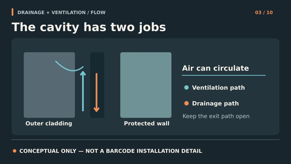
A cavity only helps when its water path and, where intended, airflow route remain connected at openings, bases, floor lines, and closures.
Key Takeaways
- Trace a continuous downhill water route to an exterior outlet at every cavity segment.
- Ventilation requires intentional inlet and outlet paths; a drainage gap by itself does not guarantee airflow.
- Screens, flashings, horizontal supports, compartment boundaries, and fire-safety details must be coordinated rather than omitted to keep a cavity open.
- Confirm cavity geometry and attachment choices for the selected wall instead of applying a generic gap or fastener rule.
Behind an aluminum panel screen, the cavity is a working part of the aluminum rainscreen assembly, not leftover space. Its first job in a drained wall is to give incidental water a route to exterior flashings and outlets. If the design also calls for ventilation, the cavity needs intentional air entry, exit, and a connected route between them. This guide is a drawing-level checklist for deciding where those routes start, stop, and change.
Draw the Water Path First
At the wall field, follow a drop of water entering a joint: it should meet the water-control plane behind aluminum cladding, pass around attachments without entering the backup wall, land on an outward-draining flashing at the next interruption, and leave the assembly. Repeat that trace at a window head, sill, base, floor line, and transition to another material. Building Science Corporation's rain-control guidance notes that drainage, drying, and water storage affect rain control; an air space can help maintain a capillary break, but it is not a substitute for continuous flashings.
Ventilation Is a Separate Design Decision
A vented or ventilated cavity uses outside air movement to help dry materials that become wet; it is distinct from merely drained or pressure-equalized rainscreen strategies. Inlet and outlet openings must be placed deliberately, and the path must remain viable around horizontal framing, flashings, screens, and other interruptions. Vent area and cavity dimensions depend on exposure, geometry, moisture loads, and the selected enclosure—not a number printed in a generic cladding article. Building Science Corporation's review of ventilated claddings emphasizes that vent locations and details matter; airflow is not established merely because a cladding has open-looking joints.
Decision Table: Check Each Cavity Interruption
Use this during detail review. Record the responsible trade and the drawing reference for each row; do not treat the table as a prescriptive installation schedule.
| Location | Drainage check | Ventilation check if intended | Coordination owner to confirm |
|---|---|---|---|
| Base and grade | Outward discharge, clearance, and no trapped water | Inlet protected without sealing the path | Architect, enclosure designer, and sitework trade |
| Window sill and head | Flashing integration and weep path | Segment continuity or deliberate reset | Window and cladding trades |
| Floor line or fire boundary | Discharge above the interruption | Do not bypass required cavity barriers | Fire-safety and enclosure designers |
| Parapet, soffit, or termination | Cap and return water away from backup wall | Outlet if the segment is intentionally ventilated | Roofing and cladding trades |
Keep Supports and Closures in the Section
Clips, rails, brackets, insulation, and terminations all occupy the same space as the water path. Draw them together in section. A horizontal support may need a designed way for water to pass or discharge above it. Required fire and cavity barriers may intentionally divide the cavity; the design must preserve their function rather than route air or water through them by assumption. Subframing and thermal-bridge control are separate checks, not reasons to omit the drainage drawing.
A Barcode Planning Example, Not a Tested Wall
Planning example only: a design team lays out Barcode panels with a starter at a façade base and a corner accessory at a return. It draws a separate outward-draining flashing below the starter and asks the enclosure professional to confirm where the cavity releases water; if ventilation is intended, it also marks inlet and outlet conditions. The Barcode catalog identifies accessory families, not an approved cavity depth, vent rate, or complete wall assembly. Confirm the current selected panel, finish, accessories, and attachment through project technical review.
Before Ordering, Review a Complete Detail
Request a base, opening, top, and representative transition section showing selected panel profile, support, water and air control layers, flashings, outlets, insulation, and any mandated cavity barriers. Coordinate cladding layout around windows and doors with those opening sections. Resolve access for inspection and cleaning where drains might clog. Physical samples can confirm profile and finish appearance, not prove rain-control performance. No universal cavity depth or fastener schedule follows from the product name; the architect and engineers must approve the project-specific assembly and installation instructions.
Frequently Asked Questions
Do aluminum cladding joints need to be sealed for a cavity to drain?
Not necessarily. Joint treatment follows the selected wall strategy. A drained wall anticipates some water behind the outer screen and provides a protected water-control plane and discharge route; the actual joint detail needs project review.
Does an open joint mean the cavity is ventilated?
No. Useful ventilation requires intentionally located openings and a connected airflow route. Framing, flashings, screens, and compartment boundaries may interrupt that route.
Can water drain through a floor-line cavity barrier?
Do not assume it can. Detail the water discharge and any required fire-safety or cavity barrier together; the responsible designers must approve the transition.
What cavity depth should I use behind Barcode panels?
No single depth applies to all projects. Coordinate the selected support and panel, water path, desired airflow, insulation, openings, exposure, and applicable code requirements with the enclosure designer and Barcode technical review.
Sources & Further Reading
- Building Science Corporation — BSD-013: Rain Control in Buildings
- Building Science Corporation — RR-0907: Ventilated Wall Claddings

About the author
Jay Zdun
Founder, Barcode Cladding
Jay Zdun is the founder of Barcode Cladding. He specializes in aluminum façade systems and helps architects, builders, and property owners evaluate profiles, finishes, and installation considerations for modern exterior projects.
Connect on LinkedIn